Using the BM612 PIR Sensor
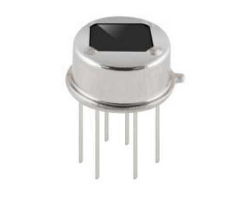
I am currently working on a project with the BM612 sensor, which is an infrared detection sensor commonly used for human presence detection. Since I could not find a concise guide on its functionalities, I decided to create one myself. This information is based on its datasheet and the SR602 module, which integrates the BM612 onto a small PCB.
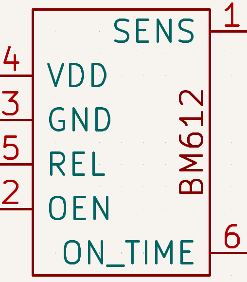
PINS
The BM612 has 6 pins. Below is a brief description of their functions.
Power Supply
The device should be powered with a voltage between $2.2V$ and $3.7V$, drawing a current no higher than $11\mu A$. Power is supplied between the “VDD” and “GND” pins.
Outputs
Detection
The system has a “REL” pin, which goes high whenever the sensor’s sensitivity threshold is exceeded. When this occurs, the “REL” pin will stay high for the duration configured in the device, as long as no further detection occurs.
Output Enable
The “OEN” pin is undocumented, but context suggests it is an “Output Enable.” If you want to disable the “REL” signal, you can connect “OEN” to ground. To allow normal operation, connect it to $V_{DD}$.
According to the datasheet, a voltage above $1.2V$ is considered a guaranteed high, and below $0.8V$ is considered a guaranteed low.
Inputs
Sensitivity
The detection sensitivity is controlled via the “SENS” pin. This determines the detection ratio, comparing active vs. inactive infrared cells.
To set the sensitivity, a voltage is applied to the “SENS” pin: maximum sensitivity occurs at $0V$, and minimum sensitivity at $V_{DD}/2$ or higher. In other words, connect “SENS” to ground to detect almost any presence, or use a voltage above $V_{DD}/2$ for stricter detection.
Detection Time
The detection time sets how long the “REL” pin remains active—effectively acting as a memory of a detection.
You can configure the detection time using the “ON_TIME” pin in two ways:
Analog
The “ON_TIME” pin generates an oscillation that determines how long “REL” stays active. The delay is calculated using the formula:
$$T_d = \frac{230400}{f}$$
A resistor and capacitor are used to set this timing: the larger the RC pair, the longer “REL” stays high. The datasheet provides tables showing the active durations.
Digital
Alternatively, the duration of “REL” can be set by applying a constant voltage to “ON_TIME”: ground for minimum time, up to $V_{DD}/2$ for the maximum time (3600s). The datasheet’s section 4.2 provides tables for the corresponding resistor configurations.
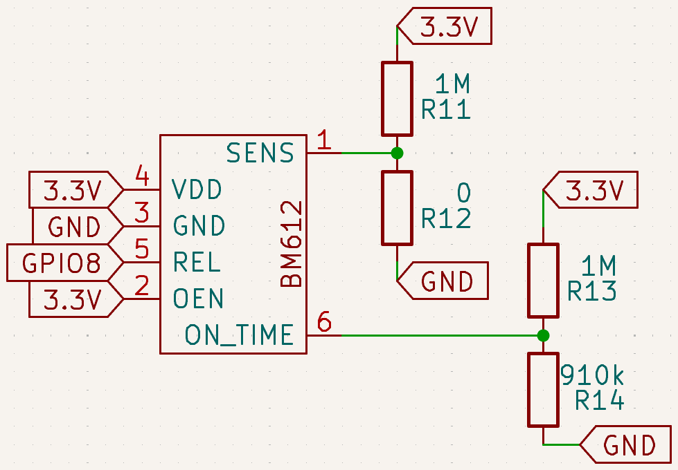
Example Circuit
The diagram shows an example circuit with the following conditions:
- Power supply: $3.3V$
- Sensitivity: connected to ground for maximum sensitivity
- Pulse duration: maximum (3600s), with voltage near $V_{DD}/2$
- Sensor always active: “OEN” at $3.3V$
- Sensor output: read by a microcontroller